The Terminal.
The unusual physics is concentrated in the QH-1 head. Downstream, the architecture is deliberately built from familiar industrial power hardware, protection, isolation, storage and conversion. The customer interface is conventional by design.
Industrial focus: 1–30 MW. The v5.3 reference assembly on this page shows three nominal 1 MW lanes; higher ratings scale the lane count and site-service package.
The quantum part has a physical shape.
The current QH-1 head fits inside a 125.4 × 111 × 96 mm envelope. Four photonic distribution rings feed 64 radiator branches around the local capture region, while the north/south electrode geometry defines the electrical pickup.
Two worlds meet here.
Dave is the boundary between the quantum protocol and the macroscopic electrical system. Measurement information arrives on the quantum side; the local extraction event closes there. From that point onward, the problem becomes recognisable electrical engineering: controlled transfer, protection, isolation, storage and conversion.
That separation is deliberate. Sensitive quantum and optical operations are kept away from the high-current backend, and the bulk-current transfer occurs after the QET transaction has closed. The machine is designed so that the strange part remains contained.
The strange part stops at the head.
A production terminal should not force an industrial customer to adopt an entirely new electrical ecosystem. The three-lane reference architecture uses components and component families that power engineers already know, document, service and replace.
Wolfspeed SiC
CAB650M17HM3T power modules with CGD1700HB3P-HM3 gate drivers in the current three-lane architecture.
Eaton protection
1000 A / 1500 VDC aR lane-fuse reference in the current industrial CAD/specification.
Schaltbau isolation
C320K/1000 isolation contactors with 24 VDC control; the auxiliary configuration is selected to the site control package.
TDK DC link
ModCap UHP B25648-family DC-link hardware, sized to lane energy and application duty.
Fujikura REBCO
FYSC-SCH12 tape geometry: 32 tapes per pole, 64 tape envelopes in the present three-lane CAD.
QH-1 optical head
1035 nm optical-control target and 64 radiator branches in the present industrial specification.
One machine. Several clocks.
Quantum hardware does not operate at household electrical frequency. The head, the measurement cadence and the conventional power electronics live on different timescales. By the time power reaches the customer interface, those internal clocks have disappeared behind ordinary power conversion.
GHz-regime and geometry-dependent. The usable work modes follow the Einstein–Rosen geometry, loaded Hamiltonian and branch-conditioned work spectrum, then overlap the QH-1 receiver response.
QET qualification / capture cadence.
Conventional C_R transfer / SiC backend.
DC or standard AC, configured for the site and jurisdiction.
A compact industrial core, scaled by lane.
The v5.3 large-unit reference assembly is the three-lane core of the 1–30 MW family: three nominal 1 MW converter lanes, one common QH-1 head and the REBCO collector. Higher ratings scale the lane count and application-specific protection, cryogenic service and site-interface package.
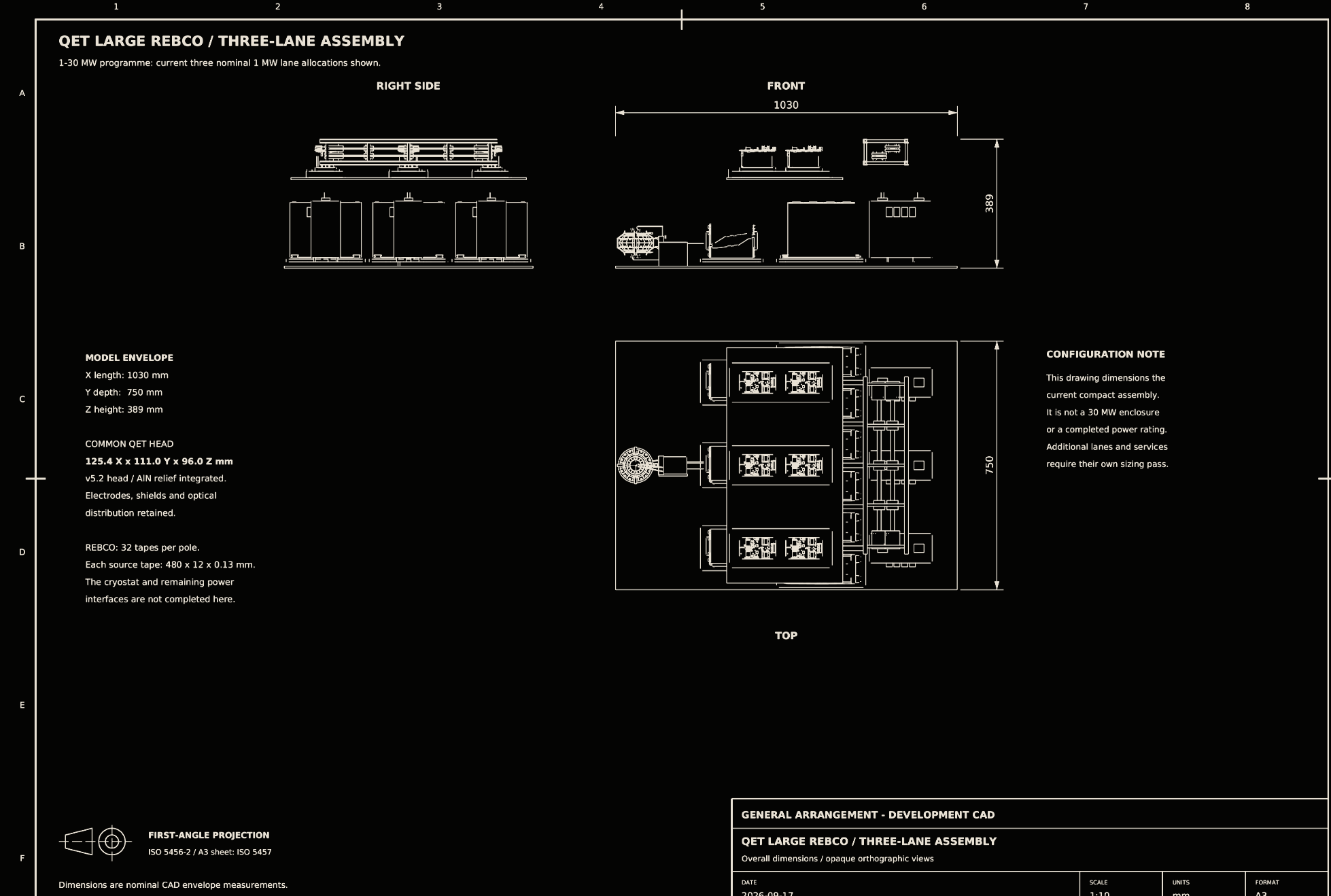
Reference assembly: 1030 × 750 × 389 mm. External cryogenic services, current leads, terminations and quench protection are configured to installed rating, site conditions and industrial load. Higher-power variants scale by lane count and service package.
A separate 10–100 kW family is also available; this page focuses on the industrial 1–30 MW programme.
The customer should not need to learn quantum mechanics.
The point of the backend is to make the unusual physics disappear behind normal industrial interfaces. The present architecture moves from the QET head into fast SiC commutation, protection and isolation, a DC-link stage, then customer-specific conversion and switchgear.
Final delivery voltage and frequency are site decisions, not quantum ones. The industrial architecture keeps the external DC/AC interface configurable while the internal reference bus is 1.2 kV DC. Standard downstream equipment can then be selected for the customer’s existing bus, protection scheme and local grid code.
Power sooner changes the economics.
Large generation projects tie up capital long before the first MWh is sold. A manufactured terminal changes that sequence: capacity is added as repeatable blocks at the load site, and each commissioned block can begin serving the customer while later blocks are still being installed.
That shortens the financing clock as well as the construction clock. Capital enters service in smaller increments, amortisation begins block by block, and the project avoids much of the fuel, long-distance transmission and civil-infrastructure burden of a conventional power station.
External benchmarks: Lazard LCOE+ 2026. FUSA figures are programme/commercial targets rather than a Lazard LCOE calculation. Lazard LCOE+ 2026 ↗
Conformity is part of the product definition.
EU production terminals are released with CE marking and an EU Declaration of Conformity. The technical file closes the applicable electrical-safety, EMC, laser-safety and RoHS requirements for the configured product.
The core standards are EN 62477-1, EN 61000-6-2 / EN 61000-6-4, EN 60825-1 and EN IEC 63000. Machinery, pressure-equipment and radio requirements apply where the delivered configuration falls within those scopes.
Electrical safety
Conforms to Low Voltage Directive 2014/35/EU · EN 62477-1 power-electronic converter-system safety.
Industrial EMC
Conforms to EMC Directive 2014/30/EU · EN 61000-6-2 industrial immunity · EN 61000-6-4 industrial emissions.
Laser safety
EN 60825-1 · 1035 nm optical subsystem · enclosed / Class 1 user boundary.
RoHS / documentation
RoHS 2011/65/EU · technical documentation to EN IEC 63000.
Conditional scopes
Machinery, pressure-equipment and radio requirements are applied where the delivered configuration falls within those regimes.